Introduction
We have already learnt about the phenomenon of a current, producing a magnetic field from various experiments especially the one conducted by Oersted.
This phenomenon came as a surprise to the scientists who discovered it. Perhaps even more surprising was the discovery of the reverse phenomenon. A magnetic field can produce an electric field that can drive a current.
This link between a magnetic field and the electric field it produces (induces) is now called Faraday’s law of induction.
Also Check: Electric fields and charges class 12 notes.
Definition:- The phenomenon of generation of current or EMF by changing magnetic field is known as electromagnetic induction (EMI).
The EMF developed in the conductor by the process of electromagnetic induction is known as induced EMF and if the conductor is in the form of closed loop, then the current flowing in the conductor is known as the induced current.
THE EXPERIMENT’S OF FARADAY AND HENRY
Let us examine three of the many experiments which were carried out by Faraday and Henry, in order to get the relationship between electricity and magnetism.
The experiments, explained below, form the basis of Faraday’s laws of electromagnetic induction.
FIRST EXPERIMENT
(CURRENT INDUCED BY MAGNETS)
Figure shows the conducting loop connected to a sensitive Galvanometer. There is no battery or the other source of EMF included, so there is no current in the circuit.
However, if we move a bar magnet towards the loop, a current suddenly appears in the circuit. The current disappears when the magnet stops.
However, if we move the magnet away, a current again suddenly appears, but now in the opposite direction.
KEY POINT:
The relative motion between the magnet and the loop is responsible for the induction of electric current in the loop. If we experimented for a while, we would discover the following :-
(1) A current appears only if there is a relative motion between the loop and the magnet (one must move relative to the other). The current disappears when the relative motion between them ceases.
(2) Faster motion produces a greater current.
(3) If moving the magnets North pole towards the loop causes, say clockwise current, then moving the north pole away from the loop causes counter clockwise current. Similarly, moving the south-pole towards or away from the loop also causes currents, but in the reversed directions.
(4) The current produced in the loop is called induced current; the work done per unit charge to produce that current ( to move the conduction electrons that constitute the current) is called an induced EMF, and the process of producing the current and EMF is called induction.
SECOND EXPERIMENT
(CURRENT INDUCED BY CURRENT)
For this experiment, we use the apparatus shown in figure 2, with two conducting loops close to each other but not touched.
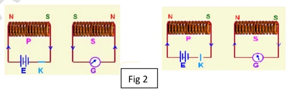
If we close key ‘K’ to turn on a current in a left hand loop, the meter suddenly and briefly registers a current –an induced current – in the right hand loop.
If we then open the switch, another sudden and brief induced current appears in the right hand loop, but in the opposite direction.
We get an induced current (and thus an induced EMF) only when the current in the left hand loop is changing (either turning on or turning off) and not when it is constant (even if it is large).
THIRD EXPERIMENT
For this experiment we use the apparatus shown in figure 3, with two conducting loops C1 and C2 carrying currents.

Galvanometer G is connected across loop C1 which is kept stationary, and loop C2 is allowed to move.
When we move loop C2 towards C1, galvanometer G shows a deflection.
Similarly, when loop C2 is moved away from C1, the galvanometer again shows deflection, but in a direction opposite to that in the previous case.
From this experiment we conclude that it is the relative motion between the two coils which induces current in loop C1 because the galvanometer shows a deflection only when C2 is in motion.
So the conclusion drawn from these experiments is that the induced EMF and induced current are caused when something changes.
Also Check: Electromagnetic waves class 12 Physics notes
Also Check: Electric Charges and Fields Class 12 Physics Notes
Also check: chapter wise class 12 physics notes
Also Check: NCERT Solutions for Class 10 Science Acids Bases and Salts
FARADAY’S LAW OF INDUCTION
On the basis of his experiments, Faraday gave out two laws concerning electromagnetic induction.
The first law deals with phenomenon and the second law gives the magnitude of induced EMF.
FARADAY’S FIRST LAW OF ELECTROMAGNETIC INDUCTION
Whenever the magnetic flux linked with a circuit changes, an EMF is induced in the circuit. In other words, “An EMF is induced in a closed loop whet the magnetic flux linked with the closed loop changes”.
EXPLANATION
In Faraday’s experiments, we find that as long as there is relative motion between the coil and a magnet, an EMF is induced in the coil.
When there is no relative motion between the coil and magnet, no EMF is induced.
It means that EMF is induced in the coil due to change in magnetic flux linked with the coil.
FARADAY’S SECOND LAW OF ELECTROMAGNETIC INDUCTION
The magnitude of the EMF ′𝜀 ′ induced in a conducting loop is equal to the rate at which the magnetic flux 𝜑B through that loop changes with time.
In other words, “the rate of change of magnetic flux is directly proportional to the induced EMF”.
EXPLANATION
In Faraday’s experiments, when magnet is moved, a galvanometer shows more deflection.
However when the magnet is moved slowly, galvanometer shows small deflection.
Hence magnitude of induced EMF varies directly as the rate of change of magnetic flux linked with the coil. This is the second law.
Mathematically, Faraday’s second law can be expressed as
Induced emf ∝ rate of change of magnetic flux.
or,
Where K is the proportionality constant and its value is K = -1, therefore we can say
The negative sign indicates that induced EMF always opposes the change in flux. The magnitude of induced EMF is calculated by dropping the negative sign.
If we change the magnetic flux through a coil of N turns, an induced EMF appear in every turn, and the total EMF induced in the coil is the sum of these individual emf’s.
If the coil is tightly wound, so that the same magnetic flux 𝜑B passes through all the turns, the total induced EMF in the coil is:
Lenz’s Law
Soon after Faraday proposed his law of induction, Heinrich Friedrich Lenz devised a rule now known as LENZ’S LAW for determining the direction of an induced current in a loop.
According to Lenz’s law, the induced current has a direction such that the magnetic field due to the current opposes the change in the magnetic flux that induces emf/current is such that it always opposes the change in magnetic flux which produces the induced emf/current.
or
“The direction of the induced emf or induced current is such that it opposes the change that is producing it”.
EXPLANATION THROUGH EXPERIMENTAL DEMONSTRATION
Let us consider a cloy circuit containing a coil C of N turns and a galvanometer G as shown.
Let a bar magnet with north-pole facing the coil is introduced into it. As the pole approaches close to coil, the magnetic flux changes.
Due to the change in magnetic flux, an induced current is set up in the closed circuit.
According to Lenz’s law, the coil will always oppose the motion of magnet, which is responsible to set up the EMF in the circuit.
So, when N pole of the magnet is moved towards the coil, the side of the coil facing the magnet develops the north polarity to repel the magnetic pole.
Closer the bar magnet to the coil, stronger is the induced north pole on the coil.
The changing flux induces a current in the circuit whose direction can be found by Right Hand Curl rule.
“Right Hand Curl rule states that if the direction of curling of fingers of right hand coincides with the direction of current, then thumb will point in the direction of lines of magnetic flux”.
Using the rule in the case above, direction of conventional current at upper face of coil is found to be anti-clockwise.
In the second part of the experiment, let the N-pole of the magnet is drawn away from the coil.
According to Lenz’s law, the side of coil facing the magnet will develop the south polarity to oppose the change.
The direction of changing flux and therefore induced current in the coil is reversed. The current through the circuit will flow in the clockwise direction at upper end.
In initial case if deflection of galvanometer was to left, it will be to right in this case.
Hence Lenz’s law is found to be true experimentally.
LENZS LAW IN ACCORDANCE WITH THE PRINCIPLE OF CONSERVATION OF ENERGY
According to law of conservation of energy, the energy can neither be created nor destroyed, but can be only transformed from one form to another form.
When N-pole of magnet is moved towards the coil, the nearer face of the coil behaves as north-pole and thus opposes the motion of incoming magnet.
Therefore, work has to be done against the force of repulsion in bringing the magnet closer to the coil.
Similarly, when the north pole of magnet is moved away, the nearer face of the coil behaves as the south-pole and thus opposes the motion of outgoing magnet.
Therefore work has to be done against force of attraction, in taking the magnet away from the coil.
It is this mechanical energy which gets converted in electrical energy. Hence Lenz’s law is in accordance with the principle of conservation of energy.
SELF INDUCTANCE
Definition:
The property of a coil by virtue of which the coil opposes any change in the strength of current flowing through it by inducing an EMF in itself is known as self-inductance.
OR
It may be defined as a property of an electric circuit due to which the circuit opposes any change of current or flux through it.
Whenever the current or the flux in the circuit has a tendency to increase or decrease, the circuit induces current in itself to oppose that change of current.
Mechanism of Self Induction
We know that any conductor carrying a current produces a magnetic field around itself. These magnetic lines or flux are linked with the circuit itself also. If the current through the circuit changes, the magnetic flux linked with it due to its own magnetic field also changes. In accordance with Faraday’s law, an EMF is induced in the circuit.
Since the magnetic flux ( Φ ) is directly proportional to the current ( I ) through the circuit:
Where ( L ) is the coefficient of self-induction and is known as the coefficient of self induction or simply self inductance.
According to Lenz’s law, the induced EMF is given as:
OR
if
Thus, Co-efficient of self-induction of a coil is defined as the induced EMF produced in the coil through which the rate of decrease of current is unity.
Units of Self Induction: SI unit of self-inductance is henry (H).
if dI/dt = 1As-1, and ε = 1V, then
Thus, the self-inductance of a coil is said to be one henry if a current changing at the rate of one ampere per second produces an EMF of one volt in it.
Dimensional Formula for Self Inductance (L):
Expanding this:
SELF INDUCTANCE OF A SOLENOID
The magnetic field due to the solenoid is:
Magnetic Flux linked across one turn of the coil is:
Since n = N/l, therefor we can write;
Magnetic Flux linked across N turns of the coil is found by multiplying the above equation by N, and is given by;
since ϕ = L I, – – – – – (B)
On comparing (A) and (B), we get
Thus, the self-induction of an air-cored solenoid depends on:
- The total number of turns (N).
- The length (l) of the solenoid.
- The area of cross-section (A) of the solenoid.
Note: Self Inductance for a solenoid wound on a magnetic material is:
Energy Stored in an Inductor
Consider an inductor of inductance L connected across a battery, as shown in the figure.

When current I flows through the inductor, an EMF ε is induced in it. This induced EMF is given by:
The negative sign indicates that ε opposes the passage of current I in the inductor.
To drive the current through the inductor against the induced EMF, the external voltage is applied. Here, the external voltage is the EMF of the battery, which is −ε, so:
Small work done by the external supply to drive an infinitesimal charge dq through the inductor is:
Since:
Therefore:
Total work done to maintain the value of current I₀ through the inductor is given by:
Integrating from 0 to I₀:
Thus, the work done in increasing the current flowing through the inductor is stored as energy U in the magnetic field of the inductor. Therefore, the energy stored in the inductor is given by:
Mutual Inductance
It may be defined as the phenomenon in which an induced EMF in a coil is set up due to the change of magnetic flux through a neighboring insulated coil.
The two coils are electrically insulated from each other. The coil through which the magnetic flux changes is known as the Primary Coil, and the coil in which EMF is induced is known as the Secondary Coil.
Mechanism and Experimental Demonstration
As shown in the circuit diagram, two coils are arranged with their axes parallel to each other. When the key is inserted in the circuit of the primary coil, the current through it increases from 0 to the maximum, and so does the magnetic flux.
The induced EMF is produced in the secondary coil due to the change in magnetic flux linked with the coil. Hence, current flows through the secondary coil, which is indicated by the deflection in the galvanometer. This phenomenon of inducing EMF is called Mutual Induction.
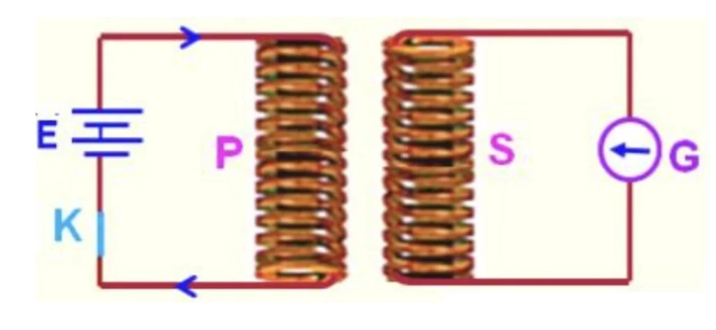
When the key K is removed, the current through the circuit decreases from maximum to 0. The magnetic flux also decreases from maximum to 0. Hence, again, the galvanometer shows a deflection due to the change in the magnetic flux linked with the coil.
Coefficient of Mutual Induction
The magnetic flux Φₛ produced in the secondary coil is directly proportional to the current Iₚ through the primary.
Where M is the coefficient of Mutual Induction or Mutual Inductance.
If Iₚ = 1 A, we get:
Thus, Mutual Inductance of two coils or circuits is defined as the magnetic flux linked with the secondary coil due to the flow of unit current in the primary coil.
Induced EMF in the secondary coil is given by Faraday’s Law of Electromagnetic Induction (EMI) as:
Since, Φs=M⋅Ip, therefore we can write,
Therefore:
Where M is the mutual inductance.
SI Unit of Mutual Inductance
The SI unit of mutual inductance is henry (H).
The mutual inductance of a coil is said to be 1 Henry if an EMF of 1 volt is induced in it due to a change of current in the neighboring coil at the rate of 1 Ampere per second.
Mutual Inductance of Two Long Co-Axial Solenoids
Consider two solenoids P and S such that the solenoid S completely surrounds the solenoid P, as shown in the figure.
Let the length of each solenoid be l and the area of cross-section of each solenoid be A. Let N₁ and N₂ be the total number of turns of solenoid P and S respectively. Let current I₁ flow through solenoid P. Then:
Where B₁ is the magnetic field due to the primary solenoid.
Magnetic flux linked across one turn of the secondary solenoid is:
Since, n1 = N1/l, therefore we can write
Magnetic flux linked across N₂ turns of the secondary solenoid is:
But:
Therefore, on comparing (A) and (B), we get
Similarly:
Thus, for two long co-axial solenoids of the same length and cross-sectional area, the mutual inductance is the same for both and leads to the principle of reciprocity:
Factors on Which the Value of Mutual Inductance Depends
The mutual inductance of two coils depends on:
- The nature of the material on which the two coils are wound.
- The distance between the two coils.
- The relative placement of the two coils.
- The geometry of the coils, i.e., size, shape, and number of turns.
Important Info
- The coefficient of coupling (K) between two coils having self-inductances L₁ and L₂ and mutual inductance M is given by:
- The value of K lies between 0 and 1.
- When K = 1, the coupling of two coils is tight, and
- When K = 0, the coupling of two coils is loose.
Motional EMF
Magnetic flux (Φ) can be changed by changing the area of the loop A, which is acted upon by the magnetic field B. Hence, EMF can be induced in the circuit.
The induced EMF produced by changing the area of a closed circuit by the motion of the circuit or part of it through a uniform magnetic field is known as Motional EMF.

The loop PQRS is slid into a uniform and perpendicular magnetic field. The change in area of the coil under the influence of the field is dA in time dt. This causes a change in magnetic flux dΦ:
Therefore, the induced EMF is:
The induced EMF is due to the motion of the loop and is called Motional EMF.
If the loop is pulled out of the magnetic field, the EMF becomes:
The direction of the induced current is anticlockwise in the loop, i.e., P′S′R′Q′P′ by Fleming’s Right Hand Rule or Lenz’s Rule.
Also Check: Notes for Class 11 Physics Chapter Waves
EDDY CURRENTS OR FOUCAULT CURRENTS
The induced circulating (looping or whirling) currents produced in a solid metal due to change in magnetic field (magnetic flux) in the metal are called eddy currents.
These currents were discovered by Foucault, so are called Foucault currents. The direction of eddy currents is given by Lenz’s law.
Eddy currents produced in a metallic block placed in non-uniform magnetic field are shown in figure below.
Applications of Eddy Currents
- Currents are used for melting iron ore, etc. (INDUCTION FURNACE).
- In speedometer eddy currents are used to measure the instantaneous speed of the vehicle.
- In electric brakes of the train eddy currents are produced to stop the rotation of the axle of the wheel. (Electromagnetic Brakes in Electric Trains)
- In Dead Beat Galvanometer eddy currents are used to stop the damping of the coil in a shorter interval.
- In Energy Meters (watt – meter) eddy currents are used to measure the consumption of electric energy.
- In Diathermy eddy currents are used for localised heating of tissues in human bodies.
Disadvantages of Eddy currents
- The production of eddy currents in a metallic block leads to the loss of electric energy in the form of heat.
- The heat produced due to eddy currents breaks the insulation used in the electrical machine or appliance.
Minimization of Losses due to Eddy Currents
Eddy currents may be reduced but not completely eliminated.
Eddy currents are undesirable since they heat up the core and dissipate electrical energy in the form of heat.
We can minimize the eddy current by the following methods:-
- The resistance of the core should be increased, to reduce the eddy current loss.
- In transformers, the thin sheets of steel in the core should be insulated from each other by a thin layer of varnish.
- As the laminations are thin, they will have relatively high resistance.
- The planes of these sheets are placed perpendicular to the direction of the current that would be set up by the induced emf. The planes of these sheets are arranged parallel to the magnetic fields so that they can cut across the eddy current paths.
- Large resistances between the sheets confines the eddy currents to the thin sheets. Each
- lamination sheet will have an eddy current circulates within it. Tiny eddy currents still exist, but only within each thin sheet, so are greatly reduced.
- The sum of individual eddy currents of all the laminations are very less compared to that of using a single solid iron core.